Et unikt konsept for LLLD sjøledninger
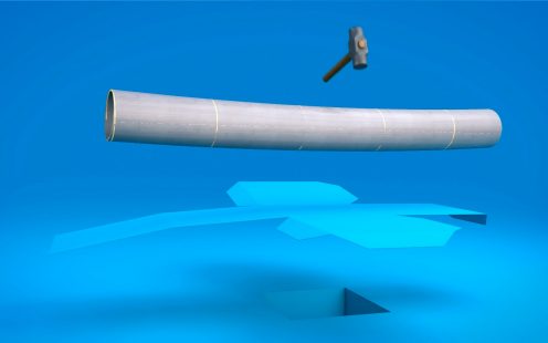
Som en ledende produsent av HDPE-rør i lange lengder med stor diameter (LLLD), tilbyr vi sikre og holdbare rørløsninger til globale marine prosjekter.
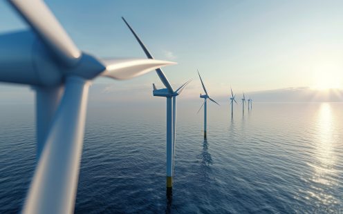
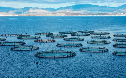
Uavhengig av tekniske eller utfordrende prosjektkrav, stoler entreprenører på vår støtte fra oppstart gjennom levering til ferdigstillelse av prosjektet. Vår portefølje av prosjekter inkluderer trykkrør til avsaltingsanlegg i Afrika, og kabelrør til vindparker i Storbritannia – i tillegg til en rekke leveranser innen havbruk, offshore og annen industri.
Interessert i en rask oversikt? Se vår video ➡
Bruksområder av LLLD sjøledninger
Din samarbeidspartner - fra a til å
Fordeler med LLLD sjøledninger
Nyheter og referanser
Production technical guide
01. Introduction to Pipelife Norge AS
Pipelife are an established and well respected supplier of polyethylene pipes and are recognised as a global leader in the supply of long length extruded solid wall PE pipes. Pipelife operate from a number of locations across Europe.
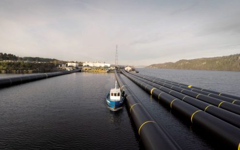
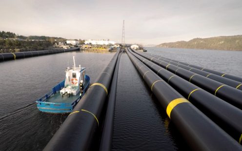
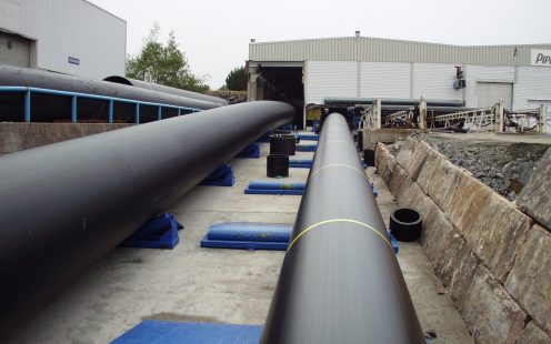
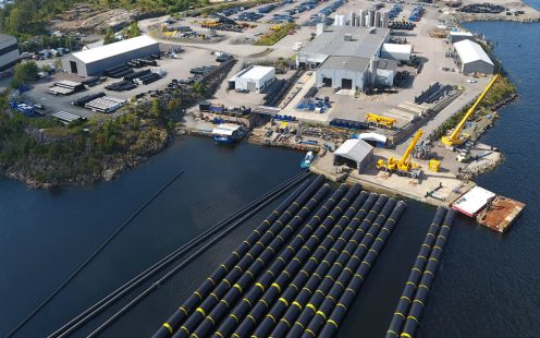
The company’s long length extruded pipelines are produced by Pipelife Norge AS in Norway. The company’s Stathelle plant is located on the shore of a protected narrow fjord, providing the perfect environment for long length pipe production. The plants position on the coast provides a number of unique benefits to enable continuous production in a clean environment and with direct access to the sea. The pipe length that can be produced is limited only by the size of the fjord itself and the diameter of the pipe. The plant has its own large storage areas on land and on sea, as well as a dedicated wharf for direct access by ocean going tugs. Norway’s infrastructure guarantees a stable energy supply and reliable provision of materials necessary for the production process.
The production line used to manufacture the pipes is of the highest quality, made with special modifications which enable unique advantages to our products.
02. Pipe range overview
Production range at a glance:
Material: High Density Polyethylene (HDPE)
Pipe diameters: OD 25mm to 2500 mm
Lengths: Standard delivery length from 12m up to 620m. (Note: substantially longer pipe lengths may be possible for some pipe diameters - please contact us to enquire).
Standard Dimensional Ratio (SDR) classes: SDR all standard values (7.4 - 33) with flexibility as described in Chapter 3.3 in detail (SDR value = Pipe OD/pipe wall thickness).
Full details are given in Enclosure 1: Pipe production range.
03. PIPELIFE’S UNIQUE PRODUCTION PROCESS AND ITS BENEFITS
In 2004 Pipelife installed the world’s first PE pressure pipe extrusion system, enabling the manufacture of PE pipes up to OD2000mm. The diameter range expansion contin- ued with the installation of an OD2500m extrusion line in 2012, allowing us to deliver pipes in OD2100mm, OD2300mm and OD2500mm. Pipelife continues to pioneer the long length large diameter PE system, pushing industry borders to provide its clients with new opportunities.
The Long Length Large Diameter (LLLD) concept was developed in the Pipelife Norge AS plant and has since proved a huge success with our clients due to the unique advantages the approach delivers.
Pipelife produces pipes using a modified pressure calibration extrusion line. To ensure that the pipe is of the highest quality, special processes are used to manufacture to consistent and reliably high standards. Some key points are mentioned in the following chapters.
3.1 Long length
Pipes are produced within controlled conditions by a continuous extrusion process using a number of purposebuilt production lines. Pipes are cut to the desired length within the process. This method of production ensures consistent quality, with no interruptions in the process. Pipe sections are fabricated in continuous lengths up to 620m in length and sealed at both ends with PE end plugs or end plate flange connections.
The maximum continuous pipe length is limited mainly by the size of the fjord, but maximum lengths can sometimes be made well beyond the width of the fjord depending on the diameter of the pipe. Please contact Pipelife for more information for a specific project requirement.
3.2 Large diameter solid wall pipe
The plant at Stathelle can produce up to OD2500mm solid wall pipe, produced according to “EN12201 – 2:2024 – Plastic piping systems for water supply, and for drainage and sewerage under pressure” and “ISO 4427-2 – Plastic piping systems – Polyethylene (PE) pipes and fittings for water supply”.
3.3 SDR classes
Pipelife’s production process enables additional benefits when determining possible SDR values for the project.
Pipelife can produce standard SDR ratios (e.g. 11, 17, 21, 26, 33) and in addition almost all other non-standard values (e.g. 13, 14, 22, 23, 24, 25, 30).
Another benefit of Pipelife’s unique process is that the SDR class can be varied throughout the length of the pipe, allowing Pipelife to tailor the pipes to the specific needs of our customers. For example, a pipe can be produced as a continuous extruded length starting with a SDR class of 26 and changing to SDR30 for the middle of the pipe with a gradual transition between the classes. This unique feature allows the production of pipe to complex specifications, such as 500 m long OD2500 mm pipe with 200 m of SDR26 and 300 m of SDR30. This feature provides flexibility and can offer substantial financial savings as higher wall thickness can be targeted at the locations where it is actually needed whilst maintaining all the benefits of a long length pipe system.
3.4 Pipe delivery by sea
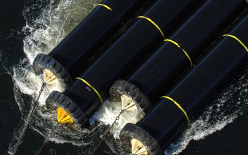
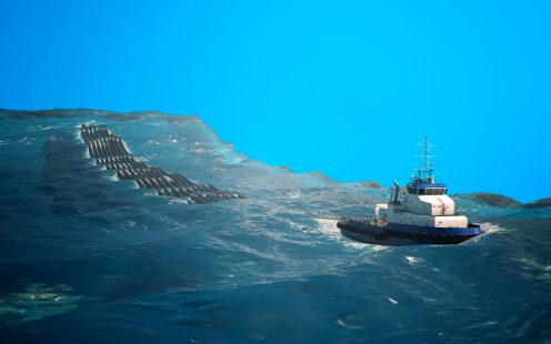
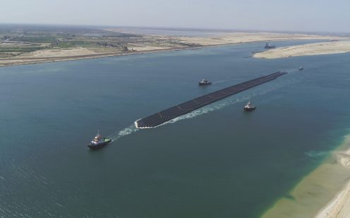
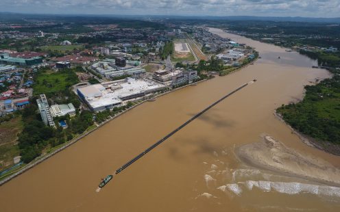
Pipelife’s towing delivery method is both effective and safe – we have done it successfully for over 50 years on over 150 projects. Individual lengths of pipes for delivery are sealed off at both ends with PE end plugs or flange connections and normally grouped into similar lengths connected by maritime towing gear. The closed pipe sections are then towed as a group by tugboat to the marine destination.
04. FITTINGS RANGE
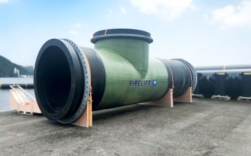
Pipelife has developed a complete range of fittings which enables the delivery of the complete pipe system, with a special focus on marine projects. Solutions have been developed for all parts of the pipeline: connection to concrete structures, pipe connections, t-pieces, bends, manholes and diffusors. These solutions guarantee longevity and excellent quality throughout the lifetime of the project, even for the largest pipes (OD2500 mm).
4.1 Branch Connections
Welded connections to smaller adjoining pipes can be provided in most size combinations. For connecting pipes less than 400mm OD, this is usually done by socket welding which forms a joint through heated fusion welding of the two pipe surfaces, similar to butt fusion welding. Where connecting pipes larger than 400mm OD are required, this is usually undertaken by electrofusion saddle jointing.
The electrofusion PE saddles have been developed as an answer to the need for safe and corrosion-free solutions for incorporating large diameter manholes and diffusors onto the main pipe. They use a specially developed electrofusion method to securely attach a connecting pipe branch to the main pipe. They have been pressure tested to more than 2 bar in full scale test conditions to confirm the quality of the welded joint. All saddles are manufactured as a single piece in PE-100 material and typically include a top flange for direct fixing of other fittings (such as riser pipes).
Saddles are available for attachment to pipes above 900mm OD in a variety of size combinations - see Table 1 for standard manufactured combinations. Other size combinations may also be available. Please consult with Pipelife for specific requirements and advice on suitable application.
4.2 PE Fittings
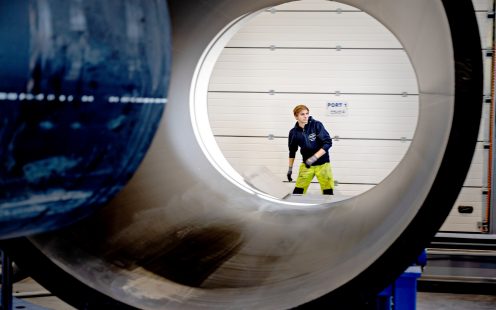
Fittings are produced as segment welded parts to form a smooth transition and ensure optimal flow and minimal hydraulic loss. Production of fittings takes place in an enclosed welding workshop located at the Stathelle plant. The workshop is equipped with various welding tables, machines, tools and saws which enable the production of any fitting up to OD2500 mm size with the only real constraint being the practical limit of transportation to the project location.
We are experienced in producing fitting types including bends, T-pieces, manhole and diffusor risers, puddle flange fittings and other bespoke elements.
All fittings produced by Pipelife are bespoke and tailor-made to suit each project’s specific requirements. Pipelife’s technical team produce 3D design models of all elements which are used to design and plan the assembly of the fittings and ensure they meet the dimensional specifications and site requirements. assembly of the fittings and ensure they meet the dimensional specifications and site requirements.
4.3 Special reinforced PE fittings
For occasions when it is necessary to increase the load bearing capacity and safety during installation, Pipelife has developed a special wrapping solution for the fittings. Wrapping protects sensitive weld areas and provides an extra layer of protection during transport, handling and installation.
05. PE MATERIAL PROPERTIES AND BEHAVIOUR
5.1 General
A solid form of polyethylene was first created in 1935 by British chemists Eric Fawcett and Reginald Gibson. This discovery was used for the first time during the Second World War in pipes that were used for the protection of radar cables. PE pipes began to be used more extensively in the 1950s. The PE raw materials have been further developed over the years and the PE resins used for pipe extrusion today are significantly improved from the resins used in the early days. PE pipe manufacturers normally purchase PE resins compounded from resin suppliers (i.e. with additives and pigments included) and do not add any further additives when extruding the pipes.
5.2 PE raw material classification
There are a number of standards used to classify PE materials for pipe extrusion. Today the most common materials used in Europe are PE80 and PE100, where the numbers refer to the long-term material strength according to EN standard. The ASTM standard for PE pipe resins classifies the strength properties of the different PE resins in a similar way, but refers to a cell classification for strength properties.
All our extruded large diameter pipes are manufactured in our factory in Stathelle in compliant PE100 resins to provide optimal strength performance. Furthermore, we typically use a PE100-RC resin, an improved variant of the standard PE100 polyethylene resin. The PE100-RC resin imparts additional low sag and high crack-resistance properties to the pipes and is the standard resin of choice for our pipes.
5.3 PE pipe classification
A PE pipe is classified by the type of PE material from which the pipe has been extruded and the SDR ratio of the pipe (pipe OD/pipe wall thickness). Alternative ways to classify PE pipes include using PN and SN values.
For further information or clarification on pipe classifications, please consult Pipelife.
5.4 PE material properties
Resin polymers for PE pipe manufacture are available in different material designations (PE 80 and PE 100). Pipelife uses only PE100 resin materials for LLLD pipes compliant with international and European standards ISO 4427 and EN 12201 from established European suppliers.
Specific properties including relevant test standards, minimum requirements and typical supplied material values are summarised in Table 2.
The allowable stress in the pipe wall of a PE pipe is normally calculated with a design factor of 1.25 on the minimum required strength value according to EN 12201. This suggests that a PE 100 pipe, which is subjected to an internal pressure corresponding to its PN designation will experience a pipe wall stress of 8 MPa, and at this stress level a lifetime exceeding 100 years at the temperature +20°C is expected. If a pipe were to be subjected to a higher pressure than its PN designation for short periods of time, it may not necessarily lead to a decreased life expectancy. A PE pipe has a significantly higher short-term strength compared to its long-term strength (approx. 23-24 MPa at a few minutes of loading and approx. 13-15 MPa at 1 hour of loading). For short-term loading conditions, the design factor is thus significantly higher. A PE pipe is therefore able to withstand higher pressures than its PN designation for short periods of time.
The strength properties of a PE pipe vary with temperature. A reduction in the pipe design stress and E-modulus should normally be applied for application in temperatures exceeding 20°C. For PE pipes to be used at temperatures higher than +20°C, the reduction factors given in Table 4 can be used. For temperatures exceeding 50°C, please contact Pipelife’s technical team for further advice. At temperatures below +20°C, strength values will logically increase slightly. However, enhanced properties are not normally applied to the design and they should instead be considered as an increased factor of safety.
5.5 E-modulus
The most important parameter for structural design in a PE pipe system is the E-modulus of the PE pipe material, also sometimes referred to as the Modulus of Elasticity or Young’s Modulus. Many formulae used for the design of pipelines require a value for the E-modulus to be selected. Since PE is a visco-elastic material, the E-modulus for a PE pipe is not a constant as it is with many other materials and appropriate values need to be selected from a set of curves or from tables to suit the design conditions. This requires a good understanding of the nature and behaviour of polyethylene under stress loading and should be determined by experienced and competent designers.
The E-modulus will determine the elongation properties of the pipe and for PE pipes it is heavily influenced by the temperature, the duration of loading and the stress level in the material. A higher temperature will give a slightly decreased E-modulus and a lower temperature will give a slightly increased E-modulus in line with the variation in strength properties indicated in Table 4. Representative design E-modulus values for pipes of PE 100 resins are given in Table 5 based on a stress level of 4 MPa in a typical PE 100 pipe at +20°C. At higher stress levels lower E-modulus values should be applied. For this reason the E-modulus is also sometimes referred to as the creep or relaxation modulus.
5.6 Ring Stiffness
The nominal pipe (or ring) stiffness is often used to describe the loading bearing capacity of the pipe. However, this can be misleading for flexible pipes as it does not define the overall ability of a supported or buried pipe to withstand a load which is usually much higher.
Where design codes refer to the pipe nominal ring stiffness (SN), values in Table 6 are provided for guidance.
Note that the ring stiffness (SN) values provided in Table 6 are based on an E modulus of 850MPa which Pipelife consider most appropriate for typical short term load response. The values may be lower than those quoted by other manufacturers for similar products as they may assume performance at a shorter (higher) E modulus value. It does not mean the pipes have an actual lower load capacity.
It is therefore very important that the designer understands flexible pipe design and is clear on the correct application of these values. If in doubt, please consult with Pipelife.
5.7 Thermal expansion and anchoring
Temperature changes or pressurising may give rise to a noticeable change in the length of a PE pipeline. As a result of this change, movements in axial direction can occur. A PE pipeline with restrained joints on supports can accommodate limited changes in length, for example minor movements and angular deflections in bends. However, consideration by the designer must be given to the potential contraction or expansion of the pipe if significant changes in temperature or pressure are expected to occur. Anchoring or restraining joints may be necessary at fittings and connections in order to limit or accommodate movements and angular deflections.
A coefficient of thermal expansion of 0.18 mm/m°C can generally be applied for the calculation of thermal movements in PE100 pipe systems.
Where axial movements are prevented in a PE pipe, the prohibited expansion will give rise to axial forces in the pipeline. Most types of joints used for PE pipes are restrained and hence the pipe system is able to transfer these forces along the pipeline and thrust blocks are not normally required. However, the designer should check that all joints can accommodate the predicted axial forces and that there are no elements that could pull apart under axial tension.
Due to the visco-elastic behaviour of PE pipes, axial forces will generally decrease over the lifetime of the pipeline as a result of relaxation in the pipe material. The initial force will depend on how fast and to what extent the pipe is elongated at assembly and how fast any temperature change occurs in the pipe. The E-modulus for calculation of the initial force should be determined from Table 5 with due consideration of the full design conditions.
Welded joints in PE pipes have almost the same strength as the pipe itself and fully welded PE systems therefore normally only require:
- anchoring of the PE pipe at connections to rigid structures such as valve chambers, and at connections to socket-jointed pipe systems.
- anchoring at each side of bends for PE pipes placed on supports.
Anchoring of the ends of PE pipelines with welded joints is usually necessary because the internal pressure will cause a small diameter increase in the pipeline, and a corresponding shortening of the pipeline will occur unless the end points are anchored. The anchoring of the end points is especially important for PE pipe placed on supports or laid in ducts. For a buried pipe, the soil friction will, to a certain extent, contribute to the anchoring of the pipe ends and constrain the axial movement. However, for large diameter PE pipes particularly, additional anchoring of the pipe ends may be necessary as the soil friction may be insufficient to prevent problematic movement at the end points.
Be aware that axial forces may be transferred from the pipe system to valve chambers and pumping stations via the pipe connections. All connection points should be designed to accommodate or resist the resulting forces, which can be large. For cast in connections, this often requires the inclusion of specific anchoring (puddle) flanges welded onto the outside of the PE pipeline. Along with the anchorage of buried PE pipes in concrete walls, the risk for water leakage between the pipe and the surrounding concrete also needs to be considered. It is therefore recommended that a cast-in PE pipe section also has a water stop flange welded on to the PE pipe.
For this purpose, Pipelife is able to provide special puddle flange fittings on request. Please contact Pipelife for further details.
5.8 Burial and backfill
In order to minimize movements at bends and tees in buried PE pressure pipelines backfill of friction material should be placed as shown in Figure 1. The backfill material is recommended to be compacted to > 90 % mod. Proctor in the following locations:
- all bends >10° at a distance of minimum 5 x OD on each side of the bend (if bends larger than 45° are substituted with two bends of half angle, an improved hydraulic function and a decreased soil pressure around the bend will be achieved.)
- all tees at a distance of minimum 10 x OD around the tee (where OD is the diameter of the branch)
Segment-welded PE tees and fittings are sometimes cast in concrete as a protection for the fitting or as thrust restraint. Where fittings are cast in, consideration should be given to whether the surrounding concrete needs to be reinforced to withstand the movement and stress from possible expansion and contraction of the pipe under internal pressure or thermal expansion.
5.9 Contaminated ground
PE pipes are generally highly resistant to naturally occurring chemicals in soils. However, they can be susceptible to some diffusion (permeation of the pipe material) from long term burial in low molecular organic substances, also termed VOCs (Volatile Organic Compounds). The level of permeability differs for different types of PE materials and increases with temperature. PE100 has a significantly higher diffusion resistance compared to most PE materials.
The time it takes for a substance to penetrate the wall of PE pipes is directly proportional to the square of the pipe wall thickness. Hence, it takes 100 times longer for VOCs to permeate the pipe wall of a 2500 mm pipe than a 250 mm pipe of the same material and SDR rating. Larger diameter pipes also have a smaller contact surface area to volume ratio. Hence, in most cases large diameter PE pipes do not need additional protection even if installed in contaminated ground. Where small diameter PE pipes are required to be installed in contaminated ground or particularly high concentrations or potentially reactive contaminants (see Chemical Resistance 5.11) are expected, pipes with a diffusion barrier can be considered.
5.10 Abrasion resistance
PE pipes have been shown to have a high level of abrasion resistance, substantially higher than other common pipe materials, including steel. Being made from a homogenous material, they are also not dependent on any surface linings which can be damaged by abrasion. At typical pipe flows (up to 5m/s fluid velocity) the amount of abrasion from potable or clean raw water can be considered insignificant.
For media containing significant levels of particulates, such as slurries, PE pipes remain one of the best choices of pipe material and they are often used for slurry pipelines in the mining industry. However, for these situations we advise that suitability should still be confirmed as the degree of abrasion can vary greatly depending on the size, shape and concentration of the solids in the flow as well as the angle of impact and flow characteristics.
For further information, please consult Pipelife.
5.11 Crack resistance
PE pipes are relatively soft and can be scratched if carelessly handled. However, they are also very resilient and do not rely on surface coatings for integrity.
The continued development of PE resins also means that crack resistant PE resin materials are now available which have reduced the amount of impact any scratches have on the strength of the pipe. Pipelife Norge prefer to manufacture all LLLD pipes from a crack-resistant resin, termed PE100-RC, which has the same strength and performance properties as PE100, but with an increased resistance to crack propagation.
Normal handling should not result in more than minor surface scratching and shallow notches which will not significantly influence the strength properties of the pipes.
Scratches on PE pipes often appear worse than they really are. The depth and significance of scratches can be measured and assessed and Pipelife are usually able to carry out specialised surface repairs to reduce the impact of deeper scratches if necessary.
Scratches up to a depth of 10 % of the pipe wall thickness will not significantly affect the strength properties of a PE pipe and localised scratches above this depth can usually still be safely accommodated with minor treatment.
For further information, please consult Pipelife.
5.12 Chemical resistance
PE pipes generally have a good level of resistance to low to medium concentrations of nearly all chemicals, salts, acids and alkalis at typical ambient temperatures (20°C). However, as a rough guide, the following substances are highlighted as potentially having a significant negative effect on the pipe material:
- petroleum products (hydrocarbon fuels) can permeate and cause slight swelling of the PE material, particularly at elevated temperatures. This typically does not cause actual degradation of the material though.
- chlorine products containing free residual (oxidising) chlorine can cause premature aging and swelling of the PE material. The effects are highly dependent on the exposure conditions. For low pressure pipe applications in marine conditions, the risk of pipe failure through material degradation from typical dosing concentrations (<5.0 ppm) can be considered very low. PE Pipes are generally considered suitable and commonly utilised as chlorination pipes.
- wetting agents and strong oxidising liquids may impair the stress cracking resistance of PE and shorten the lifetime of the pipes.
The effects will be elevated where contact substances are in high concentrations or at high temperatures (typ. >40°C) and specific consideration should given to exposure to all chemicals in these circumstances.
There is no significant material impact from permanent immersion in seawater.
Detailed information on the extent to which various chemicals may affect the lifetime and performance of PE pipes can be found in chemical resistance tables published by PE resin manufacturers and plastic pipe organisations.
For further information, or if in doubt, please consult Pipelife.
5.13 UV resistance
All pipes contain a minimum 2% carbon black content which has been proven to provide long term resistance to degradation from ultraviolet radiation. However, depending on the intensity and longevity of exposure, some precautions may be recommendable to reduce exposure and the risks of degradation, particularly for long term, above ground applications.
The effects of UV on pipes exposed to daylight for a period of up to 1 year can be assumed to be negligible. Please consult with Pipelife for more details on specific risks and guidance on UV resistance.
5.14 Hydraulic performance
For hydraulic design purposes, HDPE is classified as a ‘smooth’ material with a low surface roughness value. It is not suspectable to corrosion and is resistant to abrasion, both of which can otherwise lead to significant deterioration of the hydraulic performance over time.
Whilst it is often not separately considered in the surface roughness value, research indicates that a significant part of pipe hydraulic losses relates to the jointing in the pipe, particularly in long lengths. The long length extruded nature of LLLD pipes massively reduces the number of joints and welds and means this impact can be largely ignored. This may provide some justification and increased confidence for lower surface roughness values to be applied by the designer.
PE pipes can accommodate high flow velocities and demonstrate very good performance under transient pressure surge conditions.
Pipelife are able to assist with your hydraulic design if required – please enquire.
5.15 Carbon Footprint and Recycling
The application of LLLD polyethylene PE100 pipes delivered by sea-tow can reliably demonstrate a low overall carbon impact when compared to other pipe products in marine applications. Our solution produces very little waste product, requires minimal packaging and utilises efficient sea transportation.
There are no significant waste residues or hazardous chemicals produced in the manufacturing process that require disposal. Any waste polyethylene product created during the manufacturing process is collected for recycling into other PE products. Recycling rates within the factory are typically >95%.
Our products are made to last; typically for up to 100 years design life. The pipe material remains inert throughout its lifetime and the embodied carbon remains within the material such that in theory it can be recovered and recycled into lower grade products even at its end of life. This makes the pipe 100% recyclable and highly applicable to a circular economy.
06. WELDING
Welding is normally an integral part of every project, therefore Pipelife has invested substantial resources in determining the best possible procedure and parameters to obtain reliable results and constant improvement across the field.
All Pipelife welding is performed by trained and certified welders with many years of experience in the field. In addition, Pipelife owns and operates a comprehensive fleet of butt fusion welding machines covering the whole pipe size range.
6.1 Butt fusion welding
Pipelife has pioneered the welding process of large diameter solid wall pipes and has developed and perfected its welding techniques and procedures over its many years of direct project experience.
Pipelife Norge follows the guidelines and standards defined within INSTA-2072:2021 (Parts 1-7) for all butt fusion welding, including undertaking suitable weld sampling and testing. These standards are Scandinavian but are very similar to the more widely cited ISO 21307:2017 and DVS Technical Code 2207-1.
Butt welding is generally carried out in factory conditions where possible for maximum quality control, but can be undertaken on site if required using specialist equipment and skilled operatives. All welding is undertaken to strict quality control procedures.
07. ADVANTAGES OF LLLD CONCEPT
The Long length Large Diameter (LLLD) concept offers a cost effective and easy to install solution for offshore and near shore marine projects. Fundamentally, the concept is based on minimising the number of weak points in the system and hence the number of risks, both during installation and over the lifetime of its application.
LLLD pipes are therefore simplistic by design, but they require a high degree of manufacturing and engineering expertise and a focus on detail and quality to produce and perfect.
- With long length pipe delivery, welding/jointing work of the pipe on site can be entirely avoided. If supplied in short lengths, lengthy welding work would be required.
- Significantly reduced risk from bad welds, as very few welds are required on our long length pipes, and any necessary welds are carried out by Pipelife specialists using high quality welding rigs.
- No risks of ovalisation, as the pipes are stored in the sea. Due to the temperature difference, the pipes are free to rotate in the water, which additionally ensures the roundness of the pipes.
- No need for an on-land storage. Storing pipes on land would require large area as well as stacking limitations of pipes based on pipe size.
- Easier handling of stored pipes.
- Low environmental impact as sea transport typically has much lower carbon footprint than equivalent land transportation. Pipes are stored and handled mostly on the sea with minimal packaging or waste.
- Reduced risk of scratches and other damage to the pipes.
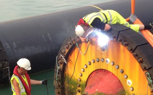
- Short installation time, and thus low installation cost. All the pipe sections are supplied with flange connections and blind flanges already on the pipe ends, so the assembly work is done at our plant. Thus, costs for the contractor are reduced.
As a result, the overall safety and reliability of the installed pipe system is substantially increased. This is of great importance to both the contractor and the client of the project.
Pipelife is focused on providing a complete system solution with product and technical support based on years of experience in marine projects worldwide.
08. MARINE APPLICATIONS
The Pipelife LLLD concept is perfectly suited for marine projects, outfalls and intakes for various purposes: power generation, desalination, sewer outfalls, sea water air conditioning, LNG terminals and floating LNG, aquaculture, industrial outfalls and intakes.
Solid wall PE pipes have an outstanding track record in marine pipe projects. Current production limitations are:
- Maximum pipe size is OD2500 mm
- Maximum supplied length for an OD2500 mm pipe is 620 m. Longer lengths up to 1500m may be feasible for smaller diameters - please enquire.
- Installation depth up to 900 m depending on the pipe size and SDR ratio.
8.1 Marine installations
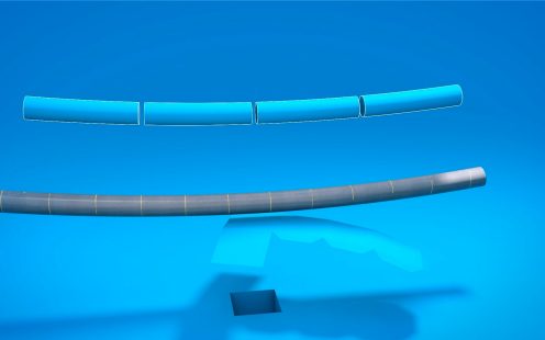
The “S-bend installation method” (also known as “Float and sink”) is a fast and economical installation method, which has been practised since the 1950s. During installation, the PE pipe can be extensively bent, and the pipe will usually be subjected to much higher stresses and strains than it will for the subsequent duration of its service life. Consequently, in order to be able to provide a good structural pipeline design, the designer should have a knowledge of marine PE pipeline installation issues.
The high degree of flexibility of PE pipes is utilized during the submersion process. PE pipes can be subjected to 5% strain without overstressing the material. However, buckling or kinking of the pipe may often occur well below this level. Therefore, it is primarily the risk of kinking or buckling of the pipe, rather than overstressing which limits the bending radius during submersion. The degree of bending at which buckling starts depends on the SDR class of the pipe.
Table 7 below shows the theoretical critical bending radius and the corresponding strain value in the pipe when the pipe will have reached 8 % ovality due to bending.
As can be seen from Table 7, buckling due to kinking is likely to occur before a strain level of 5 % is reached for all SDR classes higher than 11.
To ensure a safe installation of a PE pipe utilising the S-bend sinking procedure, the bending radius must be closely monitored during the submersion process. The bending radius is dependent on the SDR ratio, the amount of weighting on the pipe, the installation depth, the wave height during the submersion operation, the submersion speed and the pulling force applied on the floating end of the pipe.
The sinking of a PE pipe is usually in the range of 500-700 m/h, enabling the submersion operation to be fast, but safely controlled. Since the bend progressively moves along the pipeline, the bending stress will normally act on the pipe as a short-term stress (lasting only a few minutes). Since PE is a visco-elastic material, the material will creep when subjected to stress. This creep effect in the PE material will also lead to an increase in the bending of the pipe if the submersion operation is stopped or slowed down. Hence it is important to plan, monitor and control the installation process and timing carefully to avoid overstressing the pipe.
Taking into consideration the typical uncertainties involved in such operations, it is advisable to have a safety factor against buckling of at least 1.5. Furthermore, it is also advisable not to subject PE pipes to fast short term bending which could give strain values exceeding 2 % in the pipe wall. Thus, a bending radius of less than 25 times OD should not be accepted during the sinking operation even for thick-walled pipe.
For large diameter PE outfalls, operating at an internal pressure of less than 4 bar, a SDR 26 pipe will in most cases be the optimal choice. SDR 26 pipe can be bent down to a radius of 30-40 times the diameter during installation, whilst still providing a reasonably high safety factor. Recommended minimum bending radii for PE pipes of different SDR classes are provided in Table 8.
Where a pipe is proposed to be installed with a fixed curvature (i.e. permanent bending), then consideration must be given to practical issues such as installation, handling, physical restraint and the long term behaviour of the pipe. In practice, it is usually not practical to install pipes to fixed curvatures of less than 100 x pipe OD.
It is important to engage a competent marine contractor who understands these issues. In order to safeguard deep installations it is advisable to have the contractor present their method of installation, calculation of bending radius and monitoring system for the laying of the pipeline prior to the installation itself.
For further information, please consult Pipelife.
8.2 Ballasting
PE100 has a density of around 960kg/m3; a PE pipe will thus float even when filled with water if it is not ballasted. The amount of ballasting required depends on the wave and current forces that may affect the pipe, and whether the pipeline is placed directly on the sea bed or in an open excavated trench (pipelines in an open trench may be somewhat sheltered by the trench).
The pipes must therefore have concrete weights attached to ensure a sufficient stability on the sea bed against wave and current forces. The amount of loading applied largely depends on the water depth, the marine conditions and degree of exposure of the pipeline. A common weighting is in the range of 25-55 % of the pipe’s displacement, but even higher weighting may in some cases be required. There is a range of different weight shapes.
For pipes that are to be installed in trenches in the sea bed, the ballasting of the pipe is selected with regard to the risks that the pipe faces in its design life and during installation. A ballasting of 35-50 % is normally needed for such pipes, depending on pipe size and method of backfilling.
A PE pipe with concrete weights attached will tend to settle to the trench bed profile, and so the sea bed must be suitably prepared to ensure that changes in profile are gradual (to suit acceptable long term bending radii) and collars are resting on the bed. A typical weight spacing is in the range of 3-6 m depending on the amount of loading and the pipe size.
There are two important requirements, which have to be fulfilled for the discrete concrete weights:
- The weights must be attached to the pipe in such a way that they do not slide on the pipe during the sinking operation.
- The weights must be able to take the forces to which they will be subjected from the PE pipe due to the internal pressure in the pipe.
If the weights slide on the pipe during the S-bend sinking operation, the whole operation may fail. The risk of sliding is less at shallow installation depths where the angle of installation typically remains relatively low, but for pipes which are to be installed at greater depth there will be a very high risk of sliding if the matter of attaching the weights has not been properly considered. It should also be noted that the diameter of the pipe might shrink during the sinking operation due to the decreased water temperature by depth and the longitudinal forces acting on the pipe during installation.
Proper design includes testing and selecting an adequate batch of elastic material (usually EPDM rubber) for compensators and inserts between ballast weights and HDPE pipe. In addition, bolts and torque are also to be tested.
When a PE pipe is subjected to internal pressure the diameter of the pipe will increase over time. This expansion of the pipe will transfer forces to the concrete weights, and the weights must be reinforced to be able to withstand these forces. For outfalls operating at low pressures the forces transferred to the weights will be limited. However, for marine PE pressure lines, the weights must be designed to resist significant forces due to the expansion of the pipes.
For further information, please consult Pipelife.
8.3 Marine trenching and backfilling
depends on the SDR rating of the PE pipe, the external loads and the nature and compaction of the surrounding backfill material in the trench. In general, pipes of lower SDR values can accommodate substantially greater overburden loads and are therefore more suitable at high burial depths.
PE Pipes up to SDR30 can be reliably buried in trenches in the seabed with a cover of up to 5 m if backfilling with sand, gravel or crushed rock (grain size < 38 mm). Covers substantially greater than this can usually be accommodated, depending on the SDR and installation conditions, but may occasionally require additional special measures. The method of installation of the backfill should be chosen carefully in order to minimize the risk of internal material separation during installation. The method of installation must also enable the backfill material to completely surround the whole pipe, including the parts under the haunches of the pipe. The backfill material should extend at least 0.4 m above the top of the pipe. Particular consideration should be given to ensure adequate cover is provided if rock is being placed directly above the pipe. Excavated bed material can often be used as backfill around the pipe, but is subject to proper engineering and design of the whole system. Deeper installations or other backfill materials will require further calculations to check if a sufficient safety against pipe buckling can be achieved.
For advice on specific conditions or further information, please consult Pipelife.
8.4 Landfall Applications
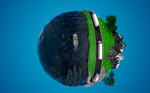
LLLD pipes are ideal for use as the permanent pipe casing in directional drill installations and have been successfully deployed in numerous installations for water and cable landfalls (offshore to inshore pipe connections). The smooth internal wall profile, gradual curvature and avoidance of joints also makes LLLD pipes perfect for applications for fish return lines where fish must be transited through the pipe unharmed.
Please contact Pipelife to enquire about how we can support these operations.
09. DESIGN AND SELECTION OF SDR
A marine PE pipeline must be designed to resist the stresses and strains to which the pipeline will be subjected to during its service life. The designer will need to select an appropriate SDR value for the pipeline noting that the worst case design condition for most marine pipeline applications is during installation of the pipe. It is noted that marine pipeline design differs considerably from traditional land-based pipe design and it should be undertaken by designers with suitable knowledge and experience.
Various load cases which will affect the selection of SDR class are:
- Out of roundness/buckling due to bending of the pipe
- Pipe buckling of buried pipes
- Expected out of roundness for buried pipes
- Pipe buckling without external support
- Loads on marine PE pipes in trenches
- Pressure and testing requirement
Pipelife are able to assist in the design if required - see Section 10. For further information, please consult Pipelife.
10. ENGINEERING AND DESIGN SUPPORT
Over the years, Pipelife has developed a wealth of specialist knowledge from its role in projects located around the world, dealing with challenging project requirements, different installation designs and methods. Many of Pipelife’s projects have been completed in cooperation with many of the world’s best consultants, engineers and marine contactors, leaving a legacy of good design decisions and successful installations.
Pipelife is committed to providing a complete system solution to help ensure the successful installation of our pipes. With its extensive resources Pipelife Norge can offer a range of specialist engineering services and general technical advice to designers, marine contractors and clients on various issues to suit specific needs and levels of support.
10.1 Design guidelines
- Determining appropriate SDR pipe class
- Review of hydraulic design: hydraulic roughness, head losses, transient and operating under pressures, ovalization, etc.
- Assessment of wave and current forces on the pipeline
- Design of weighting (ballasting) system: size, shape and spacing of blocks and block details including drawings for construction and reinforcements
- Proposal for towing head and bend restrictors
- Calculating flange connection forces and procedure for spool piecing
- Review of detailed design, drawings and method statements
- Design of corrosion protection system (sacrificial anodes)
- Calculation of pipe/soil interaction and defining backfill needs.
10.2 Installation guidelines
- Analysis of offshore pipe installation
- Determining required pull and air pressure
- Determining flooding by pumping with elevated air pressure procedure
- Determining valves for flooding and air venting
- Advice on installation risks and potential methods
- Review of drawings and method statements for pipe installation
- Review of design details due to changes in procedures and on-going support until completed installation.
For more information please contact Pipelife as each project has unique requirements and specifications.
11. TOLERANCES IN PRODUCTION
11.1 Pipe production tolerances
Pipes are manufactured to a target nominal Outside Diameter (OD). Variation in pipe wall thickness will therefore tend to produce a corresponding variation in the pipe Internal Diameter (ID).
Values for ovality and wall thickness are based on EN 12201:2024 where listed. For pipes larger than OD900 mm Pipelife has adopted the respective values in Table 9 based on the permitted maximum 3.5% ovality. It is worth noting that Pipelife’s production technique typically enables the production of pipes with an average ovality lower than 1.5%.
Wall thickness minimum and maximum values are obtained from EN 12201-2:2024 and indicated in Table 10. Values for pipe sizes and SDR ratings not listed in EN 12201 are calculated as per the recommended formula for Grade V pipes (suitable for use with mechanical fittings) in ISO 11922-1:2018: e=0,1emin+0,1 (mm).
Pipe OD is therefore produced to within -0 / +1% accuracy. Wall thickness and weight per m can typically vary by -0 / +10% above the allowable minimum value (emin). For hydraulic design it is recommended to apply a pipe ID based on 1.07*emin.
In the production of continuously extruded long length PE pipes, the following length tolerances are generally applied unless specified otherwise:
- For pipe lengths <100m: - 0 to +2 m
- For pipe lengths >100m: - 0 to +5 m
11.2 Fittings production tolerances
During the production of HDPE fittings, certain tolerances are necessary due to planning, welding and pipe production methods. Pipelife has adopted the following guideline tolerances for the production of fittings:
- For fittings and segments <Ø630: ±30 mm
- For fittings and segments >Ø710: ±50 mm
- For angle: ±3°
- All other according to EN 12201-3:2024
12. DISCLAIMER
The statements and recommendations made in this brochure are based on general assumptions and must not be considered as instructions, advice or guidelines for every individual situation. Pipelife cannot be held responsible in any way for the results of using and following the statements and recommendations made in this brochure. We especially dissuade non-professionals and consumers from operating based on the general statements and recommendations herein without any specific instructions from us or a suitably informed and qualified professional. To prevent potential damages, we strongly recommend that you consult on your individual situation with us.
If you have any queries relating to this statement, please do not hesitate to contact us.
Kontakt vår salgsavdeling
For generelle henvendelser, vennligst benytt vår felles e-post adresse - LLLD@pipelife.no
Kontaktpersoner






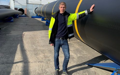
Magnus Folkestad
Project Manager Implementation and Nordic Sales
+47 415 64 602

